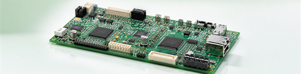
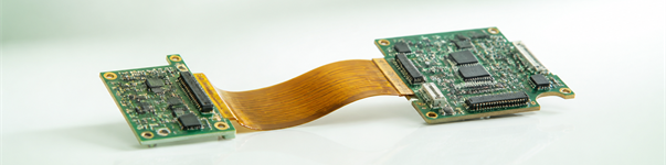
Flexible PCB & Flex Circuits
Polyimide flex circuits for dynamic bending and space-saving designs, from single-sided to multilayer rigid-flex-ready builds.
Why a flexible PCB earns its place
A flexible PCB is built on polyimide film instead of rigid laminate, so it bends, folds and fits into spaces a rigid board cannot. Donlly builds single-sided, double-sided and multilayer flex circuits, plus flex that transitions into rigid sections. When the device moves, saves weight, or must route around a tight enclosure, flex reduces connectors and failure points better than any cable harness.
Flex capabilities at Donlly
- Single-sided, double-sided and multilayer flex (up to 6 layers typical)
- Polyimide base with rolled-annealed or electrodeposited copper
- Coverlay and stiffeners (FR4, aluminum, PI) where rigidity is needed locally
- Minimum bending radius guided by layer count and copper type
- ENIG, OSP and immersion silver finishes compatible with fine pitch
Dynamic vs static bend — design for the right one
The first decision is how often the flex bends. A static-bend flex is folded once during assembly and rarely moves; a dynamic flex bends thousands to millions of times in service (think hinges and printers). Dynamic applications need thinner copper, larger bend radius and derated strain — design it wrong and it cracks. Tell us the bend cycle count and we size the stack accordingly.
Flex vs rigid vs rigid-flex
Choose flex when the board itself must move or save space; choose rigid PCB when it sits still and cost matters most; choose rigid-flex PCB when one assembly must combine both. Rigid-flex often costs more upfront but removes connectors and boosts reliability in the field.
Quality and application support
Flex boards are built to IPC Class 2/3 with AOI and electrical test, and we review bend radius, stiffener placement and pad reinforcement during DFM so the flex survives installation. Common uses: wearables, cameras, automotive sensors, medical probes and foldable consumer gear.
From prototype to volume
Start with PCB prototyping to validate the bend, then move to PCBA assembly where we place components on flex and rigid-flex and run functional test.